Use RealSimControl to map your SimulConn I/O boards in your cockpit

The Master board rev.2 has 11 connectors for cockpit controls.
1-8 connects the I/O boards through the Extension board, and 9-11 connects the serial devices like stepper motors, servo’s, and LCD’s.
Use the RealSimControl configurator to assign the I/O boards to the Arduino pins.
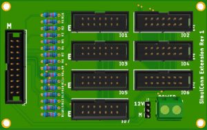 The Master board Extension Connector 1 uses ribbon cable to connect to an Extension boards M-connector.
The Extension board can connect up to 7 I/O boards ,through its IO connectors, using the following Arduino pins:
| Arduino pin number | 2 | 3 | 4 | 5 | 6 | 7 | 8 |
| Extension board connector | IO1 | IO2 | IO3 | IO4 | IO5 | IO6 | IO7 |
| SimulConn I/O board type | D/7/L | D/7/L | D/7/L | D/7/L | D/7/L | D/7/L | D/7/L |
D = 16x digital input
A = 16x analog input
7 = 8x 7-segmen display
L = 64x LED diodes
The Master board Extension Connector 2 uses ribbon cable to connect to an Extension boards M-connector.
The Extension board can connect up to 7 I/O boards ,through its IO connectors, using the following Arduino pins:
| Arduino pin number | 9 | 10 | 11 | 12 | 13 | 20 | 21 |
| Extension board connector | IO1 | IO2 | IO3 | IO4 | IO5 | IO6 | IO7 |
| SimulConn I/O board type | D/7/L | D/7/L | D/7/L | D/7/L | 7/L | D/7/L | D/7/L |
D = 16x digital input
A = 16x analog input
7 = 8x 7-segmen display
L = 64x LED diodes
The Master board Extension Connector 3 uses ribbon cable to connect to an Extension boards M-connector.
The Extension board can connect up to 7 I/O boards ,through its IO connectors, using the following Arduino pins:
| Arduino pin number | 30 | 31 | 32 | 33 | 34 | 35 | 36 |
| Extension board connector | IO1 | IO2 | IO3 | IO4 | IO5 | IO6 | IO7 |
| SimulConn I/O board type | D/7/L/P | D/7/L/P | D/7/L/P | D/7/L/P | D/7/L/P | D/7/L/P | D/7/L/P |
D = 16x digital input
A = 16x analog input
7 = 8x 7-segmen display
L = 64x LED diodes
P = PWM
The Master board Extension Connector 4 uses ribbon cable to connect to an Extension boards M-connector.
The Extension board can connect up to 7 I/O boards ,through its IO connectors, using the following Arduino pins:
| Arduino pin number | 37 | 38 | 39 | 40 | 41 | 42 | 43 |
| Extension board connector | IO1 | IO2 | IO3 | IO4 | IO5 | IO6 | IO7 |
| SimulConn I/O board type | D/7/L/P | D/7/L | D/7/L | D/7/L | D/7/L | D/7/L | D/7/L |
D = 16x digital input
A = 16x analog input
7 = 8x 7-segmen display
L = 64x LED diodes
P = PWM
The Master board Extension Connector 5 uses ribbon cable to connect to an Extension boards M-connector.
The Extension board can connect up to 7 I/O boards ,through its IO connectors, using the following Arduino pins:
| Arduino pin number | 44 | 45 | 46 | 47 | 48 | 49 | 50 |
| Extension board connector | IO1 | IO2 | IO3 | IO4 | IO5 | IO6 | IO7 |
| SimulConn I/O board type | D/7/L | D/7/L | D/7/L | D/7/L | D/7/L | D/7/L | D/7/L |
D = 16x digital input
A = 16x analog input
7 = 8x 7-segmen display
L = 64x LED diodes
The Master board Extension Connector 6 uses ribbon cable to connect to an Extension boards M-connector.
The Extension board can connect up to 7 I/O boards ,through its IO connectors, using the following Arduino pins:
| Arduino pin number | 51 | 52 | 53 | A0 | A1 | A2 | A3 |
| Extension board connector | IO1 | IO2 | IO3 | IO4 | IO5 | IO6 | IO7 |
| SimulConn I/O board type | D/7/L | D/7/L | D/7/L | D/A/7/L | D/A/7/L | D/A/7/L | D/A/7/L |
D = 16x digital input
A = 16x analog input
7 = 8x 7-segmen display
L = 64x LED diodes
The Master board Extension Connector 7 uses ribbon cable to connect to an Extension boards M-connector.
The Extension board can connect up to 7 I/O boards ,through its IO connectors, using the following Arduino pins:
| Arduino pin number | A4 | A5 | A6 | A7 | A8 | A9 | A10 |
| Extension board connector | IO1 | IO2 | IO3 | IO4 | IO5 | IO6 | IO7 |
| SimulConn I/O board type | D/A/7/L | D/A/7/L | D/A/7/L | D/A/7/L | D/A/7/L | D/A/7/L | D/A/7/L |
D = 16x digital input
A = 16x analog input
7 = 8x 7-segmen display
L = 64x LED diodes
The Master board Extension Connector 8 uses ribbon cable to connect to an Extension boards M-connector.
The Extension board can connect up to 5 I/O boards ,through its IO connectors, using the following Arduino pins:
| Arduino pin number | A11 | A12 | A13 | A14 | A15 | ||
| Extension board connector | IO1 | IO2 | IO3 | IO4 | IO5 | ||
| SimulConn I/O board type | D/A/7/L | D/A/7/L | D/A/7/L | D/A/7/L | D/A/7/L |
D = 16x digital input
A = 16x analog input
7 = 8x 7-segmen display
L = 64x LED diodes
The Master board stepper/matrix connecter is connected to the serial interface of the Arduino.
| Arduino pin number | D18 | D19 | ||||
| Stepper/Matrix connector | 1,2 | 3 | 4 | 5,6 | ||
| Connection | VIN | Tx1 | Rx1 | GND |
| Arduino pin number | D16 | D17 | ||||
| Stepper/Matrix connector | 1,2 | 3 | 4 | 5,6 | ||
| Connection | VIN | Tx2 | Rx2 | GND |
| Arduino pin number | D14 | D15 | ||||
| Stepper/Matrix connector | 1,2 | 3 | 4 | 5,6 | ||
| Connection | VIN | Tx3 | Rx3 | GND |

The Possibility of a Non-Pilot Landing a Commercial Airplane
The Possibility of a Non-Pilot Landing a Commercial Airplane – seen with Flight Simulator Training Perspective In a scenario reminiscent of cinematic drama, the idea

The essential role of cabin pressure
The essential role of cabin pressure in air travel 2024 Hello, fellow aviation enthusiasts! In this article, we will dive deep into a crucial element

Boeing 737 – the world most flown airplane
Boeing 737 – the world most flown airplane The Boeing 737, affectionately known as the “baby Boeing,” boasts a history spanning over five decades, showcasing

The future of Flight Simulation
The future of Flight Simulation The world of flight simulation has come a long way from its rudimentary beginnings. Gone are the days when simulating
Which flight simulator is best in 2024?
Which flight simulator is best in 2024? Choosing Your Virtual Skies: X-Plane 12, Prepar3D, or MSFS 2020 – Navigating the Best Flight Simulator for Your
What is ILS landing?
Instrument Landing System (ILS) is a critical component in aviation, ensuring precision during the approach and landing phases. Pilots rely on ILS to guide the